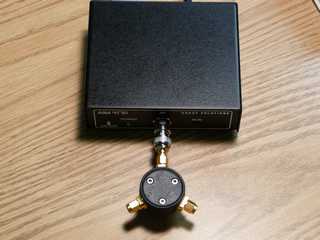
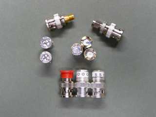
The tests were done over the range of 1 to 170 MHz and only the AIM4170 and the HP8753B were compared.
The precise measurement of impedance at microwave frequencies is an art and can even be challenging at 170MHz. A section of coax with velocity factor (VF) of .7 (typical of teflon coax) 1.0 cm. long causes 2.9 degrees of rotation on the Smith Chart. This seemingly small amount of cable changes impedance values significantly for impedances that are far from the center of the Smith Chart.
When accuracy is important, knowing the reference plane is critical. The approach to calibration taken by HP with the HP8753B is very different from what is done with the AIM4170 as is shown below.
Bob Clunn, W5BIG was kind enough to build me a beta version of the software that does line extension (software ver. 6.55 and later will include line extension) so that I could match the reference planes with the 2 network analyzers. Line extension is purely a mathematical concept extending or removing of a lossless piece of coax cable which has a definable length, impedance, and velocity factor.
I could not find anything written about reference planes and BNC connectors. All references seem to be in regards to more precision connectors such as APC-7mm, APC-3.5mm and type N. The APC connectors are sexless and are totally flat so the reference plane is obvious. I did find some antecdotal evidence that the reference plane for SMA connectors is where the dielectric materials meet between the two connectors. Since I own HP calibration standards that are type SMA I connected a high quality BNC-M to SMA-F adapter to the front of the AIM4170. I also connected a precision APC-7mm to SMA-F adapter to the HP8753B. Now both analyzers had the same connector.
Calibration and Reference Plane
Page content last updated Mar. 12, 2008
Copyright © 2008 Larry Benko, W0QE
Click on any pic for higher resolution image
The tests consisted of 2 loads designed to be high SWRs on opposite sides of the Smith Chart. Inaccuracies in the analyzers are much more apparent with high SWR loads.
Load #1 = Four 22 ohm 5% 0603 SMT resistors in parallel + the BNC to SMA adapter. Due to the number of low value resistors I would expect this load to be slightly inductive at the plane where the resistors are connected.
Load #2 = Four 2.7k ohm 5% 0603 SMT resistors in parallel + the BNC to SMA adapter. Due to the number of high value resistors I would expect this load to be significantly capacitive at the plane where the resistors are connected.
Load #1:
AIM4170: @ 170MHz. Z = 5.87 + j9.122 ohm (SWR = 8.8:1)
HP8753B: @ 170MHz. Z = 5.89 + j9.152 ohm (SWR = 8.8:1)
Load #2:
AIM4170: @ 170MHz. Z = 73.7 - j204 ohm (SWR = 13.3:1)
HP8753B: @ 170MHz. Z = 74.9 - j202 ohm (SWR = 13.0:1)
Load #2:
AIM4170: @ 1MHz. Z = 669 - j13.1 ohm
HP8753B: @ 1MHz. Z = 672.4 - j14.0 ohm
These comparisons are amazingly close!
Other tests I have done on various antennas, filters, and components showed a very good agreement between the 2 analyzers. Of course at HF the importance of getting the reference planes correct and the precision of the standards is not nearly as critical.
Then I did a custom calibration on the AIM4170 from 1 to 170MHz with a .25MHz step size. For the HP8753B I loaded the disk that came with the calibration standards into the analyzer and did a calibration from 1 to 170MHz with 401 points. After calibrating, the following impedances were measured and were quite interesting.
AIM4170:
"Short" standard connected @ 170MHz. Z = 0.0 + j.077 ohm (very good short as expected)
"Open" standard connected @ 170MHz. Z = 22k - j57k ohm (very good open as expected)
"50 ohm" standard connected @ 170 MHz. Z = 49.9 + j.03 ohm
Bare SMA-F connecter (standard removed) Z = 1.8 + j1534 ohm (not a very good open)
HP8753B:
"Short" standard connected @ 170MHz. Z = 0.05 + j1.78 ohm (not good)
"Open" standard connected @ 170MHz. Z = 0.01 - j1488 ohm (not good)
"50 ohm" standard connected @ 170 MHz. Z = 50.00 + j.004 ohm (virtually perfect)
Bare SMA-F connecter (standard removed) |Z| > 30k ohm (msmt. erratic but a very good open)
The HP8753B, after doing an internal calibration, compensates for the length of the standards (the open and short are different by a round trip delay time of just over 2 pico-seconds), imperfections in the standards (primarily fringing capacitance in the open standard) and sets the reference plane to be the edge of the dielectric on the SMA-F connector. However the AIM4170 does no such correction and assumes that the reference plane is some where within the standard. Understanding this concept explained previous unsuccessful attempts to compare measurements between the two analyzers. The HP standards measure ~0.9cm to the reference plane and are constructed with an air dielectric which should have a VF very close to 1.
I set the line extension to be -0.9cm, 50 ohm, VF=1 in the AIM4170 software. The distance was negative since we wish to move the reference plane closer to the analyzer by 0.9cm. The following data was then observed.
AIM4170 with line extension set to -0.9cm, 50 ohm, VF=1:
Bare SMA-F connecter (standard removed) |Z| > 60k ohm (msmt. erratic but a very good open)
Voila, now both analyzers show an extremely high impedance at the SMA connector at 170MHz and are calibrated for the same reference plane.
Comparison Measurements
More measurements continue on the next page.


