Click on any pic for higher resolution image
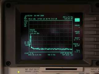
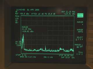
Noise floor consisting of only the input DC power supply and a 0.75 ohm load (~14A) without the battery booster. Signals on left side of screen are the AM radio stations.
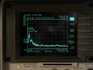
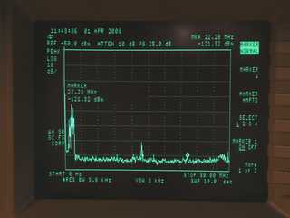
Common mode current on power input cable. Load = 0.75 ohm + lead resistance (~19A).
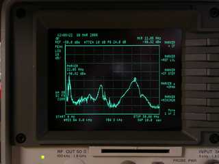
Unit as delivered with 6 foot cables on both ends. Common mode current peak around 22 MHz caused S3 spurious signals to be received on an all band antenna approximately ~20 feet from battery booster. The common mode currents at ~22 Mhz are about 7uA and need to be reduced about 20dB. The signals around 11 MHz were only S1 and the hash from about 2 to 8 MHz was not heard.
Common mode current on power output cable. Load = 0.75 ohm + lead resistance (~19A).
Each power lead was wrapped through an FT240-43 toroid 8 times close to the battery booster. The enable/disable wire was wrapped through a smaller toroid 6 times but the external switch was later mounted inside the unit. All the toroids provide > 1000 ohms of impedance over the frequency range of 3 to 30 MHz and have been verified via a network analyzer several times previously. The reduction in noise was huge. There was still some under 8MHz stuff to reduce but I did not hear this over the air. The conclusion section at the bottom of the page has links where to find the toroids.
Common mode current on power input cable. Load = 0.75 ohm + lead resistance (~19A). Spikes at ~13MHz were externally generated.
Common mode current on power output cable. Load = 0.75 ohm + lead resistance (~19A). Common mode current at 22MHz very slightly visible but no longer able to be heard.
Common mode current on power output cable. Load = 3.3 ohm + lead resistance (~4A).
Common mode current on power output cable. There was No Load (0A).
Page content last updated May 21, 2008
Copyright © 2008 Larry Benko, W0QE
I was looking for a battery boost circuit or product for use while operating mobile with the vehicle engine off. A battery booster is basically a switching power supply that delivers an output voltage of nominally 13.8VDC when the input voltage is less than 13.8VDC. Many HF mobile radios "really" want a little more voltage than you get from a 12V car battery with the engine off especially as the SWR rises above 1:1. Click here for some power output versus voltage measurements I made on an Icom 7000 and an Icom 706mkIIG in a mobile environment. Additionally a battery booster will keep the radio from resetting, due to low DC input voltage, when starting the vehicle.
I decided to buy a N8XJK Marine Booster from TG Electronics as the initial step. This product contains the same battery boosting circuitry as their other products but does not have features like RF sense and variable delay which I did not plan to use. The reviews on this product have generally been good but I have a friend who had one and said his unit generated some noise. The use of a battery booster will normally be in a setup where the receiving antenna is located very close by and consequently needs to be exceptionally RF quiet. The RF sense feature is one way around any possible interference where the unit only boosts the voltage during transmit. However I often operate full QSK CW and the unit does not boost and then stop boosting at the CW keying speed. Therefore I wanted a unit that would be enabled 100% of the time and still be RF quiet. By having the unit enabled 100% of the time I would also not reset the radio when starting the vehicle. If this device produced a lot of RF interference I would need to go to plan "B" and design something. Generally I would rather design something I have a passion about and battery boosting isn't it.
I decided to buy a N8XJK Marine Booster from TG Electronics as the initial step. This product contains the same battery boosting circuitry as their other products but does not have features like RF sense and variable delay which I did not plan to use. The reviews on this product have generally been good but I have a friend who had one and said his unit generated some noise. The use of a battery booster will normally be in a setup where the receiving antenna is located very close by and consequently needs to be exceptionally RF quiet. The RF sense feature is one way around any possible interference where the unit only boosts the voltage during transmit. However I often operate full QSK CW and the unit does not boost and then stop boosting at the CW keying speed. Therefore I wanted a unit that would be enabled 100% of the time and still be RF quiet. By having the unit enabled 100% of the time I would also not reset the radio when starting the vehicle. If this device produced a lot of RF interference I would need to go to plan "B" and design something. Generally I would rather design something I have a passion about and battery boosting isn't it.
Test setup and the base noise level
Stock unmodified unit
External large toroids
Start of Modification
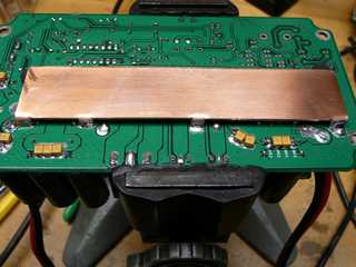
I was pleased with the results of the large toroids but they are nearly as large as the product itself. I decided to see what I could do inside the unit with no external toroids. The circuit board was extracted from the enclosure after removing all the glue that made the unit water resistant (hence marine use). The circuit board was very nicely made with ground everywhere and stitched together in hundreds of places. The basic layout looked good. I touched up a couple of solder joints that looked like they needed to have been made with a slightly larger soldering iron but that was cosmetic at best. I had talked with Tim Gerdeen at TG Electronics and he told me the new circuit board had a bunch of capacitors on the bottom of the board to help with the RF interference. I removed all these 1uF ceramic capacitors and repackaged the circuit board in the enclosure and did another test without any external toroids. Good, the conducted current on the power lines exiting the unit was now worse than before. Then I took the circuit board and removed the solder mask in many places and added a combination of 40 2.2uF tantalum and .1uF ceramic capacitors (picture below left) everywhere I could bypass the input and output voltages to ground. Another repackage, test, and the common mode currents were now about 6dB better than the stock product. Now I tried a huge 1" wide, .040" copper bus to connect the ground together better (picture below right) and that change made absolutely no difference. Darn, after machining the copper to fit I didn't want to remove it so I left it in place.
Addition of 40 capacitors. About 6dB improvement at 22MHz and slightly less elsewhere.
Addition of 40 capacitors and ground plane. No additional improvement.
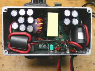
In addition to the capacitors on the bottom of the circuit board which moderately helped and the ground bus which was of no value I decided to try to fit the largest torroids I could fit inside the enclosure. I used 2 Steward 28B1020-100 u=850 (43 material) 1.02"OD x .50"ID x 1.125" long. This is the same as an Amidon FB(43)-1020. I could squeeze 3 turns through this toroid giving about 400 ohms of common mode impedance at 3.5MHz and 1600 ohms at 30MHz. While this wasn't nearly as much as the big external toroids it was all that would fit. Then I plugged the old exit holes for the cables, made new holes, and bypassed the power leads to the case, after the torroids, with parallel .22uF and 1000pF ceramic caps using the shortest leads possible. All 4 power leads were bypassed this way. Yes I know that carving away the insultaion to make the connections isn't too cool but it does work and given the space seemed like the only choice as shown in the picture below. I mounted the remote enable switch on the enclosure no longer making it "remote".
Final Modifications
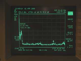
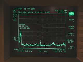
The measurements on the final modifications are shown below. The large external toroids were slightly better at 22MHz but the under 8MHz stuff is much better with the internal modifications. The 22MHz noise has been reduced more than 25dB from the unmodified unit. I was going to try some external toroids in addition to the internal modifications but I need a screen room to make these kinds of measurements. For reference, the common mode noise produced by my cell phone AC charger is at least 10dB above these numbers below 20MHz tapering off to about the same level at 30MHz.
Final Measurements
All pictures on the page can be clicked on for a higher resolution image
Common mode current on power input cable. Load = 0.75 ohm + lead resistance (~19A).
Common mode current on power output cable. Load = 0.75 ohm + lead resistance (~19A). Spikes at ~13MHz were from external source and were periodic.
Common mode current on power output cable. Load = 3.3 ohm + lead resistance (~4A).
Common mode current on power output cable. There was No Load (0A).
Conclusions
The reviews posted by many people indicate that they hear no interference from this device. However they might not have looked hard enough or in the right places. They may also have other noise sources masking what they hear. Also coupling from the common mode current on the wires leaving the battery booster to the radio antenna is extremely variable. The coupling is related to the distance between the wires and the antenna, the length of the wires and their orientation etc. However the design of a product to be used in a mobile environment needs to be extremely quiet since the radio antenna will normally be in close proximity so being as quiet as possible is important. I realize that the modifications I made are not going to be done by most people. However the simple addition of the two external large toroids will make a huge improvement if you do hear any interference. These toroids are 2.4" OD x 1.4" ID x 0.5" thick and made of #43 material (permeability 850). Wind each of the power cables 8 times through a toroid close to the battery booster. Amidon, Fair-Rite, Steward and others are some manufacturers. Digikey (www.digikey.com) sells the Steward 28B2400-000 toroid (Steward's 28B material is the same as #43 material). Also Amidon (www.amidoncorp.com) sells the FT-240-43 toroid.
The unit never needs to be disconnected from the battery since the quiescent current draw is about 1.3mA (when boosting is disabled) and about 27mA (when boosting is enabled). I mounted the unit next to the radio and adjusted the boosted output voltage to be 14.0VDC (no load) which drops to about 13.8VDC (with a 19A load) and the unit runs cools with normal 100W transceiver operation. The wiring from the booster to the radio can now be lighter wire such as #14 since a few tenths of a volt drop no longer affect the radio. Likewise the unit delivers 13.8VDC output for all input voltages above about 9.5VDC resulting in longer parked operation with the engine off and no longer resetting the radio when starting the car engine. By having access to the enable/disable switch the boosting can be turned on and off while listening to the radio in the receive mode to verify that there is no noise present. However the unit does drop the input voltage by about .45V (1 Schottky diode drop) in the disabled mode. As mentioned earlier I leave my unit enabled 100% of the time the radio is on. The unit ceases boosting and passes the input DC input voltage through a Schottky diode to the output should the input voltage rise above the set boosted voltage.
The unit never needs to be disconnected from the battery since the quiescent current draw is about 1.3mA (when boosting is disabled) and about 27mA (when boosting is enabled). I mounted the unit next to the radio and adjusted the boosted output voltage to be 14.0VDC (no load) which drops to about 13.8VDC (with a 19A load) and the unit runs cools with normal 100W transceiver operation. The wiring from the booster to the radio can now be lighter wire such as #14 since a few tenths of a volt drop no longer affect the radio. Likewise the unit delivers 13.8VDC output for all input voltages above about 9.5VDC resulting in longer parked operation with the engine off and no longer resetting the radio when starting the car engine. By having access to the enable/disable switch the boosting can be turned on and off while listening to the radio in the receive mode to verify that there is no noise present. However the unit does drop the input voltage by about .45V (1 Schottky diode drop) in the disabled mode. As mentioned earlier I leave my unit enabled 100% of the time the radio is on. The unit ceases boosting and passes the input DC input voltage through a Schottky diode to the output should the input voltage rise above the set boosted voltage.
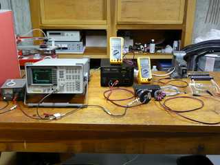
The unit was promptly received (Mar. 29, 2008) and preliminary bench tests looked good so out came a spectrum analyzer, low noise preamplifier (24.5dB, 2.9dB NF), and a current probe to measure what noise was leaving the unit as common mode current on the wires. The above left picture shows the setup with the large toroids on the power leads. Click on any image for a high resolution version. I measured the unit under the conditions of no load, light load (~4A), and heavy load (~19A) which the unit handles easily for long periods of time. I do not have an EMI screen room and the current probe sees every radio, TV, FM, and louder short wave radio stations when clamped on any wire. Also I did not use a line impedance stabilization network (LISN) as is done in professional tests in order to equate the common mode currrent on the leads to a V/m field strength. The current probe I used had a sensitivity of 0 dB-ohm meaning 1A of current through the probe produces 1V into a 50 ohm load. To make the math easier -87dBm on the spectrum analyzer is 10uA of current. Likewise -97.5 dBm is 3uA, -107 dBm is 1uA, and -117.5dBm is 0.3uA. The current probe used covers the range of 100KHz to 100MHz. Generally if the currents on the leads are below 0.5uA they never are able to be heard. The spectrum analyzer plots are swept from 10KHz to 30MHz with a 3KHz bandwidth.
